Introduction
Task 2 composed of creating a portion of a motorcycle's fuel tank at the scale of 1:1, using the techniques learnt from assignment 1, 3D Software, and laser cutting machines. Starting in groups of 10 with students from architectural studies. construction management, and landscape architecture we chose the fuel tank of a Yamaha IT250, the more challenging of the three because why not? (At this stage it was unknown to us how complex the tank was). Over the next 3 weeks we mapped the tank digitally; created a 3D model, sliced and lasercut this model into a template, sectioned off the tank, and then began model shaping. This assignment taught us the properties of aluminium as a material, digital processes of photogrammetry, and further enhanced our skills as a metal worker.
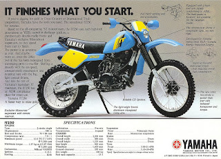 |
| The bike from which the tank is from |
 |
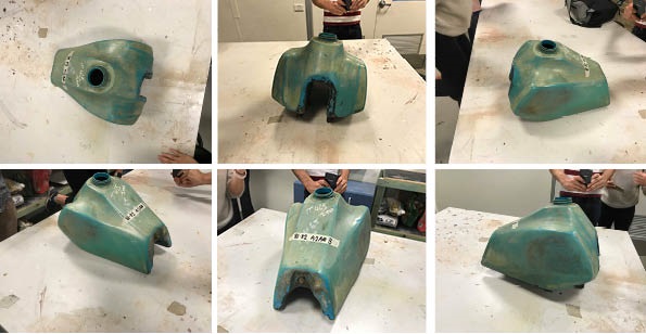
| 1:1 real tank |
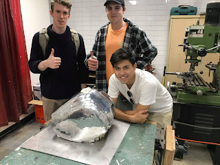 |
| Our group of three, (from left; Remy, Jake, Me), with the finished tank! |
Step 1: Photogrammetry, Recap & Slicer
Tools/Equipment:
- 1:1 Tank
- Camera
- Fusion 360
- Laser cutter
- Computer with ReCap, Illustrator, Slicer
To start off with we took images with our mobile phones from 360" perspectives all around the tank. The photos had to be captures every 10" for the software to be able to map the image. Then we imported the images to ReCap which maps common points and creates a 3D image. After a smooth 3D model was created, it was imported into slicer which turns the model into a waffle model, to create the template for the laser cutter.
 |
| Creating a 3D image for photogrammery |
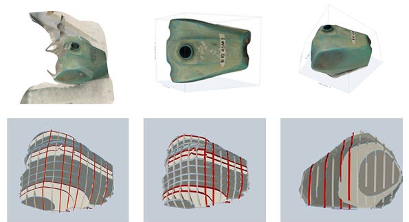 |
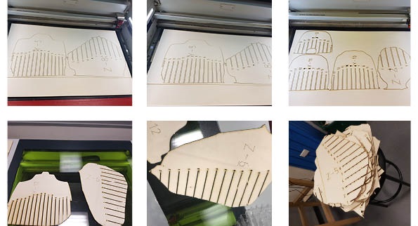
Top row: Images from ReCap (after importing 2D photos),
1st from left, trial image, 2nd & 3rd, successful trial after more images
Bottom row: screenshots from slicer getting ready to laser cut |
Step 2. Laser cutting and assembling the template
Tools/Equipment:
- Masking Tape
- Glue
- Markers
- Laser cutter
- Plywood
After Slicer sliced the 3D model into .dxf's for the laser cutter to read, it was imported and cut out of plywood. After the initial thought of having 30 slices on each axis resulted in too much plywood, we decided to increase the caps between slices . This reduced the total sheet count down to 12, which was more viable. DXF's exported from slicer were placed into illustrator, where the colour had to be changed to red for the laser cutter to read 'cut', and then fed into the laser cutter.
 |
| Laser cutter cutting the .dxf's from slicer |
 |
Finished template pieces from the laser cutter
|
Once the template was cut out from the laser cutter it was assembled and glued together and left to set.
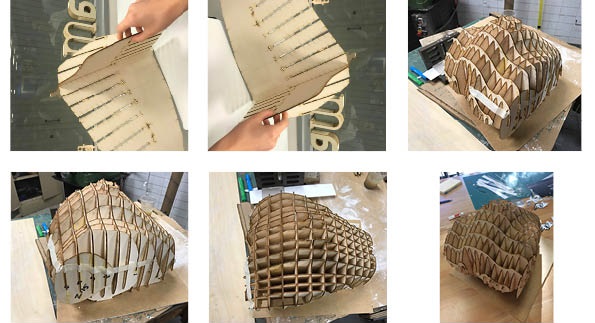 |
Assembling and gluing together the template
|
Step 3: Pattern making and thinking
Tools/Equipment:
- Masking tape
- Marker
- Paper
- Scissors
- Aluminium sheets
- Tin snips
- Guillotine
Now that we had a template cut out, it was time to start thinking about metal shaping and pattern making. Upon comparing our template to the 1:1 tank it was discovered that the template was larger than the real thing. This can be attributed to scaling in ReCap. Where as we chose the diameter of the tank lid to scale the template to the real thing (a relatively small measurement), we should have chose the largest measurement (perhaps the length of the tank), so that upon scaling, the range of error is shortened.
It was time to split into groups of 3 and we began diving the tank into 3 parts for us to form out of metal. Myself, Remy Dunne, and Jake Fornasaro set about beginning this task, as it was soon learned that due to the many apexes, curves, reflection and bends, 3 equal pieces of metal would not be feasible.
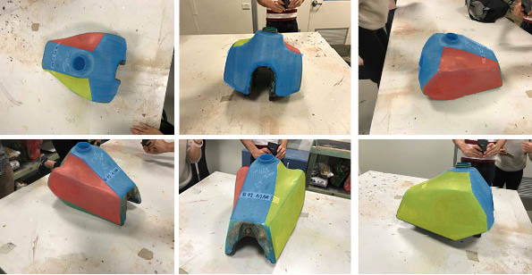 |
Blue: Jake, Red: Remy, Yellow: me.
Divided into portions which would allow for the most efficient and cleanest joins |
We then covered the template in masking tape to understand the curves of the form, and began to mark out each section along the strongest joins.
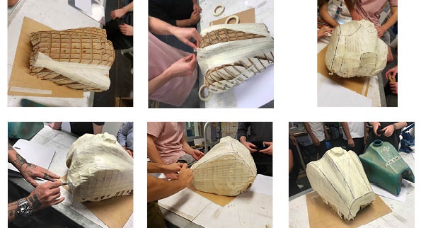 |
| Covering it in tape, getting help from the tutors of the best way to third the tank, and marking out each piece |
Once we divided the tank into 3 portions (around 6 pieces) it was time to use paper to wrap around the template to create a 3D skin into a 2D shape which we can transform onto the sheet metal. Paper allowed us to wrap it around the template without stretching, which made it easy to create a 2D template from a 3D shape. Then, we could trace this around our sheet aluminium and get a rough shape.
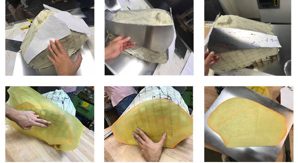 |
| Pattern making: transforming a 3D skin to a 2D shape |
After doing all of the preliminary work in groups, it was now time to split up and shape the metal into it's form.
My pieces were split into 2 forms:
- A torus-like shape which starts at a point that stretches out to connect the side panel to the top face, which had a slight curve before dipping to join the front panel.
- A distorted bowl-like shape for the side panel, however it was not circular, it had concave both in and out, and had to join the piece above and the front panel
Step 4. Shaping metal
Tools/Equipment:
- Permanent marker
- Tape
- Aluminium
- English wheel
- Guillotine
- Various nylon headed mallets
- Sandbag
- Plywood stump
- Metal scribe
- Vice
- File
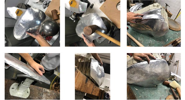
Shape 1
I first started with the torus-like panel which connected the side and upper skins. I first began marking out the bends of the metal, and then pinched it with various hammers to get a bend along its x and y axis.
Creating the drop down towards the front face of the tank for this piece proved to be the hardest part (if I had to do this again i would make a sharper curve so when i evened it out it would align better, instead of bending it at the end).
 |
Early stages of shaping.
|
After the rough shape was created, I marked it over the template and trimmed around the edges to get a cleaner piece. It's much easier to bend less metal so get the rough shape first. If you cut too close to the boundary that is fine as the metal is easy to stretch.
 |
| More marking and shaping to align with the template. |
Once I had a rough shape it was still difficult to bend the top of the piece. I had to English wheel the end of it substantially to stretch the metal enough for it to allow me to bend it into my desired shape.
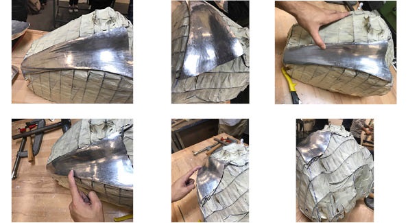 |
90% finished
|
Finally after stretching the metal I had shaped it as close to the template as I needed, for this stage. At this stage it is 70% finished. I left it now so that the final shaping can be aligned to my side panel, before polishing and finishing the piece.
Shape 2:
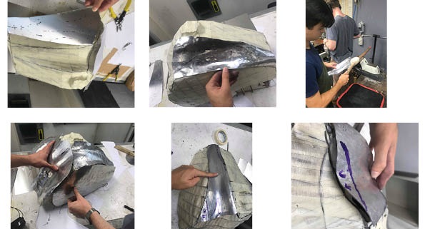
After getting most of the first shape done, it was time to start the side panel of the tank. After pattern making and cutting out the shape, I pinched the metal to get the general concave's and convex's of the side panel. Then I english-wheeled it smooth and trimmed it, before leaving the top edge to align with the side panel which sits above it.
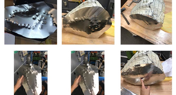 |
| Pinching the metal to shape the concave, rough english-wheeling to smooth it out |
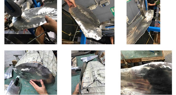 |
| More english-wheeling and shaping |
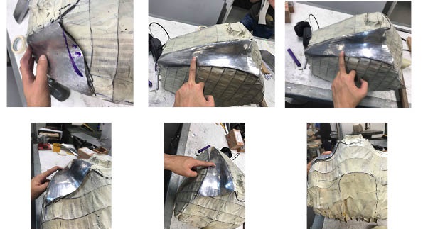
After getting the rough shape by using the english wheel and pinching the metal, I pinched it from the front to get the concave shape on the other side. Once I did this, the metal became distorted as seen in the middle bottom row picture above. I had to then mark and stretch the metal to bend back to the template.
 |
| Test fitting and more trimming |
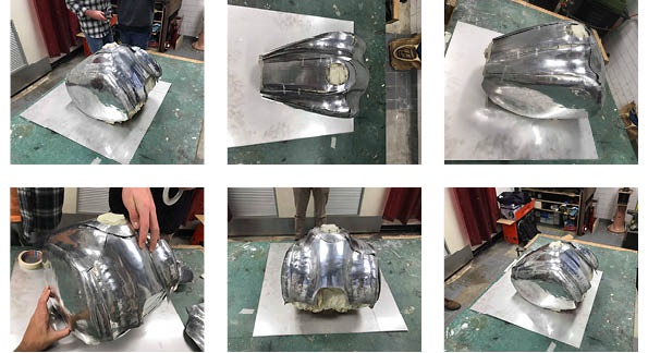
By now, I test fitted the metal with its other surrounding parts to get an idea of the overall shape. Keep in mind that every other piece is around 70% done and so the shape is looking very rough.
 |
| Rough fitting of everyone's pieces |
 |
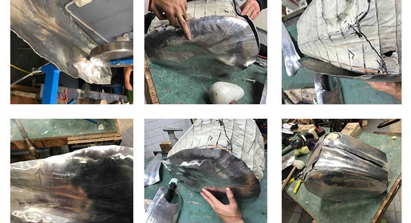
| Smoothing and shaping close to the final shape |
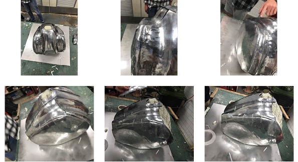
Once I had test fitted it roughly, I could begin to smooth and shape the piece more carefully, and in relation to the piece's it fits.
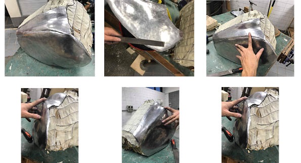 |
| The pieces finished and overlapping smoothly |
In the first image on the top row on the left, the pieces fit smoothly but there is still a gap. I then filed the edge and smoothed them out to overlap with less gaps. At this stage, they are 90% finished. I just need to finish the pieces with some brasso and do the final shaping once all the final pieces are present.
Step 5: Finishing
Tools/Equipment:
- Brasso
- Rags
- Gloves
- Disk Polisher
I'll admit, I probably did not have to begin polishing the pieces now when they are 90% done and not 100%. However, I was bored and didn't have access to the template over the weekend so I decided to try out the disk polisher with some brasso. In fact, by polishing them it allows me to see the imperfections more clearly as the light reflects, showing the small bumps and cracks more clearly. Now when I do my final light test fitting and smoothing, it is more clear and I only need to supply a small amount of polish.
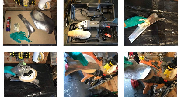 |
| Progression of polishing |
Below are some test photos of the final pieces - keep in mind I have to shape them marginally to the template, other piece's, and smooth out part of the shape
Step 6: Completed Photos
After some light smoothing and filing, I am finally finished! Here are photos of my individual pieces on the tank, and as a finished piece with my groups other pieces to make up the whole tank.
 |
| My two pieces joined to make the tank with other group members pieces |
 |
| More focus on my two pieces and how they fit together |
Some final images:
Reflection
Upon completing this project I can reflect on a few things, both on the craft of metal working, and how it integrates into my area of study- architecture. Once I began to study each section I would be making, it was quickly apparent how many apexes, curves, twists and bends in conflicting places, were on each piece. Soon it became clear how the metal would want to bend one way, and not the other. If I could do it again, I would definitely over compensate with the bends, so when it came to shaping the metal the other way it would even out more easily.
The possibilities through shaping metal seem endless, while through programs such as autocad, sketchup, and to a lesser extent rhino, I work in very defined parameters. Now with this appreciation for metal, and the shapes it can take, I can look at incorporating more fluid, sculptural pieces in my designs and projects which I would not have considered without this new found interest in the form of sheet metal. Applications could stretch from small interior details, to large forms built around metal sheeting.


